Simple inverter based on arduino (what is arduino?)
I have been an electronic hobbyist for past 10 years and I am still learning. During the past 4 years I got busy with lot of other things and did not have enough time to pursue my hobby. Couple of months back I bought an arduino kit and got interested in it. Having spent quite sometime (thanks to my wife who helped me in understanding simple programs) with the kit and making simple projects I decided to make something useful.
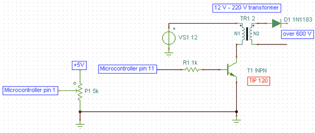
I learned long time back that the famous 555 chip can be used to control the brightness of an LED or to control speed of a motor based on the principle called Pulse-width modulation(PWM). One can also achieve the same function using an ardunio and this is what I intended to show here. The electronic circuity and its operation is very simple (shown below). The pulses from the micro controller are fed to base of the transistor through the 1 K resistor which in turn switches the low voltage side of transformer On and Off. The pulse width is controlled by the potentiometer P1. This circuit can used to drive a modified CFL (with out the electronic circuity) or series of bright white LEDs whose brightness can be controlled by the potentiometer P1. The source code for the program can be downloaded by clicking the file below.
I learned long time back that the famous 555 chip can be used to control the brightness of an LED or to control speed of a motor based on the principle called Pulse-width modulation(PWM). One can also achieve the same function using an ardunio and this is what I intended to show here. The electronic circuity and its operation is very simple (shown below). The pulses from the micro controller are fed to base of the transistor through the 1 K resistor which in turn switches the low voltage side of transformer On and Off. The pulse width is controlled by the potentiometer P1. This circuit can used to drive a modified CFL (with out the electronic circuity) or series of bright white LEDs whose brightness can be controlled by the potentiometer P1. The source code for the program can be downloaded by clicking the file below.
| pwm_cfldrive_dec25a.pde |
Disclaimer:Please note that the high voltage produced (also potentially lethal !!!) cannot not be used to drive any sensitive electrical/electronic devices and I take no responsibility for any damage whatsoever.
